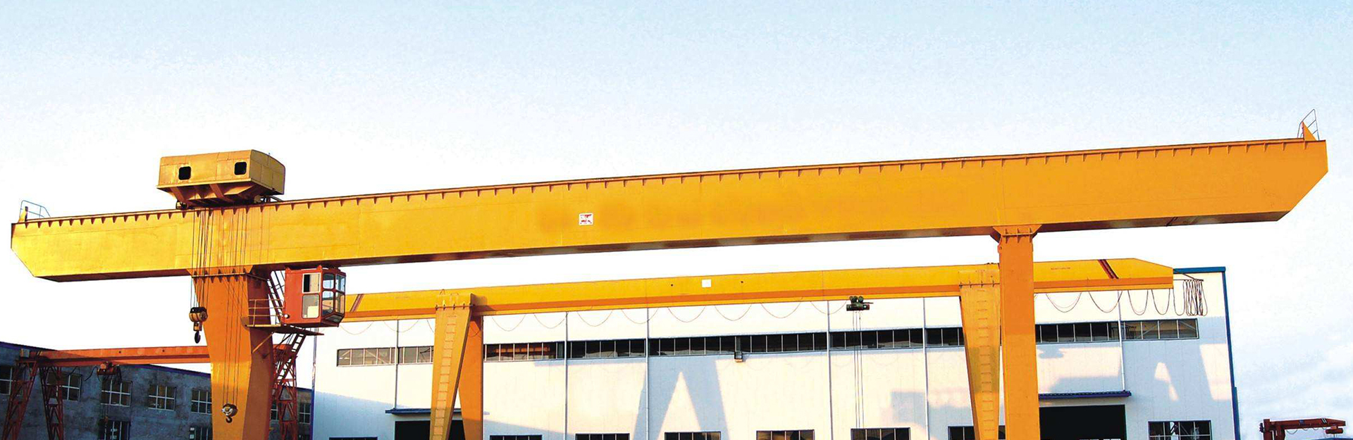
Today, the manufacturer of Shandong gantry crane introduced to you the causes and solutions of the non magnetic failure of the electromagnetic suction cup.
The electromagnetic suction cup has no magnetic force. Cause of fault:
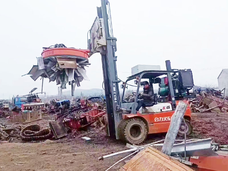
In fact, many people don't know that the internal parts of the disk need to be replaced and repaired frequently, and the excitation coil is also easy to burn out. Even if the parts are not damaged, it is also easy to fail, resulting in no magnetic force of the small magnetic chuck.
The magnetic line of force comes out of the n-stage of the magnet, passes through the yoke, passes through the ferromagnetic workpiece, and then returns to the yoke and enters the s-stage of the magnet. In this way, the workpiece can be firmly absorbed on the working surface. When the magnetic level is in the state, the magnetic line of force is less than the working level surface, and a closed circuit of the magnetic circuit is formed inside the small magnetic chuck. Almost no magnetic line of force comes out of the working level surface, so there will be no suction on the workpiece, and the unloading can be realized smoothly.
Solution to the non magnetic fault of the electromagnetic suction cup:
1. Open the power distribution box of the CNC machine tool, check the power at both ends of the fuse with a test pencil, and then measure the power supply voltage of 380V with a multimeter at the AC 500V gear. Disconnect the main power switch, check whether the AC contactor is mechanically stuck, remove one coil and one wire of the contactor, and measure the resistance at both ends of the coil with a multimeter resistance block. If the indication of the gauge needle is normal, it proves that the coil is good.
2. Connect the coil and wire, remove the undervoltage relay housing, measure the resistance at both ends of the coil, and the gauge needle still indicates that the undervoltage relay coil is not open circuit, and then check whether the relay is mechanically stuck.
3. Close the upper power switch, measure the voltage at the secondary side of the transformer with the AC Gear of the multimeter as 135v, and change the DC gear to measure the voltage at both ends of the rectifier diode. Under normal circumstances, the DC voltage output by the bridge rectifier should be 110V, and there is no voltage output at this time.
4. Disconnect the main power switch, measure the four rectifier diodes respectively with the resistance gear of the multimeter, and it is found that there are problems in two of them. Weld the wire connecting the secondary pipe, remove the secondary pipe, and conduct measurement and inspection again to prove that the secondary pipe has been broken down. Replace two new secondary pipes, connect the wires, weld them, and check whether the welding is firm.
5. Use the DC gear of the multimeter to measure the two ends of the rectifier diode. There is a voltage indication, and the voltage value is 110V. The operator presses the button of the grinding wheel motor and starts the circular electromagnetic chuck switch. The workpiece can be sucked, indicating that the fault has been eliminated.
The above content is a detailed introduction to the causes and solutions of the non magnetic fault of the electromagnetic chuck, and I hope it will be helpful to you.
 2022-4-2